TECHNICAL REQUIREMENTS FOR THE PRODUCT
| INOUT OF THE NORM | |
| Aluminum and aluminum alloys. Extruded profiles with increased precision from alloys: EN AW-6060 and EN AW-6063. Permissible deviations in dimensions and shapes of profiles EN 12020-2:2001 | |
- Basically, the profile is intended for building structures
- Increased requirements regarding the decorative and front surface of the profile;
- The maximum circumscribed circle diameter is less than 300 mm;
- Produced with increased precision in size and shape.
1. Permissible deviations in dimensions other than wall thicknesses
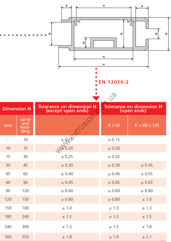
2. Permissible deviations in the wall thickness of closed and open profiles.
Dimensions in millimeters

If, for functional reasons, permissible deviations of both external and internal dimensions of closed profiles (profiles with a hole) are indicated, then the deviations indicated in Table 2 should not be applied as permissible deviations in wall thickness, but as permissible deviations for differences in wall thickness. The difference should be determined by measuring the maximum and minimum wall thickness drawn in the same plane.
PRODUCTS
SERVICES
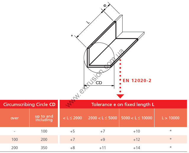
3. Length tolerances
If the supplied profiles are to be of an exact length, this must be stated in the order. Permissible deviations of the exact length are indicated in the table
4. Permissible deviations of straightness
Straightness deviations should be measured in the manner shown in the figure below, placing the profile on a horizontal marking plate in such a way that its weight reduces the deviation.
Permissible deviations of straightness must correspond to those indicated in the table.
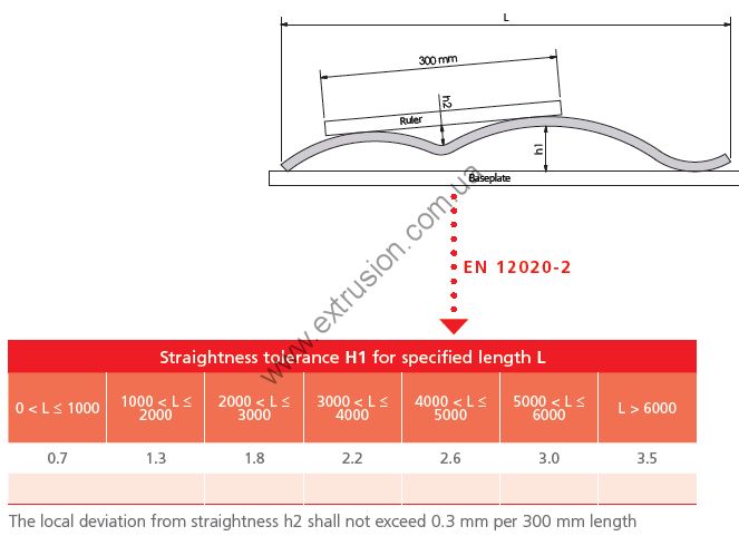
Straightness deviations on sections up to 300 mm of the profile length should not exceed 0.3 mm.
5. Convexity - concavity
Convexity - concavity should be measured using the method shown in the figure. The permissible values of convexity and concavity must correspond to those indicated in the table.

In the case of open and closed profiles with a width W greater than 150 mm, the deviation on any section of width W1 100 mm, should not exceed 0.5 mm.
6. Contour

7. Twisting
Torsion should be measured in the manner shown in Figure 1, by laying the profile under its own weight on a marking plate and measuring the maximum distance anywhere along the length of the profile between its bottom surface and the surface of the marking plate. The permissible twist values depending on the width and length are indicated in the table.

8. Permissible angle deviations

The maximum permissible deviation a from an angle other than a right angle must be ± 1°
In the case of unequal lengths of the sides, you should take the angle deviations for the side that is shorter, that is, start the measurement from the side that is longer.
9. Characteristics